
A force can change translational motion, but its ability to create rotation depends on more than magnitude. Push a door near its hinge and it responds weakly; apply the same force near the handle and it rotates readily. Push directly toward the hinge and the door may not rotate at all. Torque measures this rotational effectiveness about a chosen origin or axis. It combines the applied force, its location, and its direction into one rotational quantity.
Torque is not simply “a force that turns.” It is a property of a force relative to a selected axis, so changing the axis can change the torque. The concept supports rotational dynamics, angular momentum, structural equilibrium, biomechanics, and machine design. This lesson builds the vector definition, derives the lever-arm form, and develops a sign-consistent equilibrium workflow. Units and diagrams accompany each stage so that formulas remain connected to physical meaning.
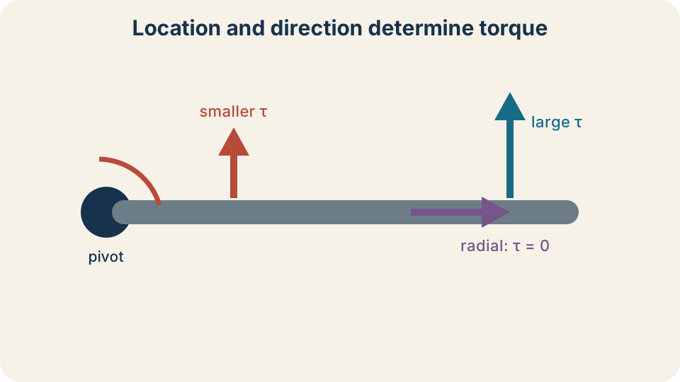
The same force can create different torques about the same pivot. A longer position vector usually provides more rotational leverage. Only the component perpendicular to the position vector contributes. A force whose line of action passes through the pivot produces zero torque. The curved arrow indicates the tendency to rotate, not the path of the force.
Identify the system and axis first
Every torque statement requires a system and a reference axis. The system identifies which body or collection of bodies is being analyzed. The axis identifies the line about which rotational tendency is measured. In a flat diagram, the axis is often perpendicular to the page through a selected pivot point. The same applied force can have different torques about two different pivots.
Consider a force applied to a horizontal bar. About the bar’s left end, the force may have a substantial moment arm and produce a large torque. About the force’s own point of application, its position vector is zero and so is its torque. Neither result contradicts the other because they answer different rotational questions. Always mark the chosen axis before substituting numbers.
Axis choice can simplify equilibrium problems. Choosing a pivot through an unknown support force makes that force’s moment arm zero. Its torque then disappears from the rotational equation even though the force still acts. The remaining torque equation may isolate another unknown directly. This is a strategic coordinate choice rather than a physical claim that the support force has vanished.
Define torque with a cross product
Let be the position vector from the chosen axis to the force’s point of application. Let be the applied force. Torque is defined by . The bold Greek letter , pronounced “tau,” denotes the torque vector. The cross symbol denotes a vector product rather than ordinary multiplication.
The magnitude is , where , , and is the smaller angle between the two vectors when placed tail to tail. The sine factor selects the part of the force perpendicular to . Parallel force contributes no torque because . Perpendicular force produces the maximum magnitude for fixed and because . Angles between the vectors must be measured from a shared tail.
The torque direction is perpendicular to the plane containing and . Curl the fingers of the right hand from toward through the smaller angle. The thumb then points in the torque-vector direction. In a two-dimensional page, that direction is either out of or into the page. A sign convention commonly assigns counterclockwise torque as positive and clockwise torque as negative.
Understand the perpendicular force component
Any force can be resolved into components parallel and perpendicular to . The parallel component is . It pulls or pushes along the radial line and produces no instantaneous turning effect. The perpendicular component is . Substituting into the magnitude relation gives .
Suppose a force acts from an axis at to the position vector. The perpendicular component is . The torque magnitude is . Using the full force without the sine factor would incorrectly produce . The angle must be defined between the actual vectors, not guessed from a nearby surface.
This component view is useful when a force arrow is already drawn from the application point. Draw or imagine the radial line from pivot to that point. Resolve the force relative to that radial line. The component perpendicular to the radial line creates rotation. The component along it changes internal loading but contributes no torque about the selected axis.
Use the perpendicular moment arm
Torque magnitude can also be written . The symbol is the perpendicular distance from the axis to the force’s line of action. A line of action is the infinite straight line passing through the force vector. Geometry gives . Therefore and are equivalent descriptions.
The moment-arm form often avoids component calculations. Extend the force arrow into a straight line, then measure the shortest distance from the pivot to that line. That shortest segment must meet the line of action at . Multiplying its length by the full force gives torque magnitude. Measuring along the bar instead of perpendicular to the line of action is a common error.
If a force’s line of action passes through the axis, the moment arm is zero. The force may be large and may accelerate the center of mass, yet its torque about that axis is zero. A radial force on a wheel illustrates this condition. Torque describes rotational tendency about a point, not the overall importance of a force. A zero torque does not mean a zero force.
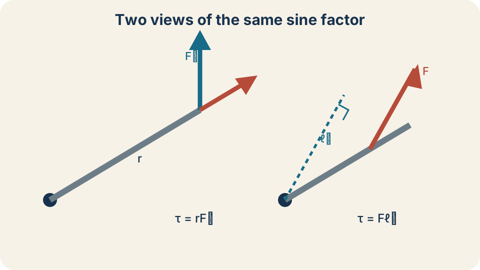
The left construction multiplies radius by the perpendicular force component. The right construction multiplies the full force by the perpendicular moment arm. Both produce . The two right triangles contain the same sine factor. Choose the construction that is clearest in the given geometry. Do not apply both perpendicular corrections at once.
Keep torque units distinct from energy
The SI unit of torque is the newton metre, written . It follows directly from force in newtons multiplied by distance in metres. One newton is , so torque has base units . These dimensions match those of a joule. Nevertheless, torque and energy are different physical quantities.
Energy is a scalar, while torque is an axial vector with direction and sign. Work by a constant torque involves an additional angular displacement: when torque is aligned with the angular displacement and constant. The angle is measured in radians and is dimensionless in SI analysis. Thus torque times angle yields energy. Writing torque in joules would hide the distinction between rotational tendency and transferred energy.
Units provide a diagnostic in numerical work. A reported torque of lacks the required distance factor. A reported value of uses an energy name for a torque calculation. A moment arm in centimetres must be converted to metres before producing SI torque. For example, .
Work an opening-door example
A force is applied perpendicular to a door from its hinge. The position vector runs from hinge to application point, and the force makes a angle with it. The magnitude is . Since the sine equals one, . The right-hand rule determines whether the signed torque is positive or negative.
Apply the same force only from the hinge. The new magnitude is . Quartering the radius quarters the torque when force and angle remain fixed. This proportionality explains why door handles are placed far from hinges. It also explains why long wrenches make a given hand force more effective.
Now apply the force at the handle but at to the door’s radial direction. The torque is . Only half the force is perpendicular in this geometry. The remaining component points along the door toward or away from the hinge. Moving farther out cannot fully compensate if the force direction becomes poorly aligned.
Sum torques with a sign convention
Several forces can create competing rotational tendencies. Choose counterclockwise as positive and clockwise as negative before calculating. Determine each torque’s sign from the actual tendency about the pivot. Then calculate the signed sum . The sigma symbol instructs us to add every torque included in the system model.
Suppose a downward force acts to the right of a pivot, while an downward force acts to the left. The right-side force tends to rotate clockwise, giving . The left-side force tends counterclockwise, giving . Net torque is , so the net tendency is clockwise. The negative final sign carries directional information.
Do not assign signs from whether a force points up or down alone. A downward force on the left and the same downward force on the right produce opposite rotational tendencies. Sign depends on force location relative to the pivot as well as direction. A quick curved-arrow sketch prevents many errors. Keep every torque signed until the final physical interpretation.
Distinguish force equilibrium from torque equilibrium
Static equilibrium requires both and . The first condition prevents translational acceleration of the center of mass. The second prevents angular acceleration about the chosen axis. Either condition alone is insufficient for a rigid body. A pair of equal and opposite forces can have zero net force while producing nonzero torque.
Such a pair is called a couple. Imagine one upward force on the right side of a steering wheel and an equal downward force on the left. Their vector sum is zero, yet both tend to rotate the wheel in the same direction. Their torques add rather than cancel. This example separates translational balance from rotational balance clearly.
Conversely, zero net torque about one axis does not automatically prove zero net force. A single force applied through the selected pivot has zero torque about that pivot but can accelerate the object translationally. Static equilibrium requires checking both vector conditions. In planar problems, this usually means two force-component equations and one torque equation. The three equations address three independent possible motions.
Solve a balanced-beam problem
A uniform beam of mass is supported at its center, and a child sits to the left of the support. Where should a child sit on the right for rotational equilibrium? Choose the support as the pivot. The beam’s weight and support force both act through that pivot, so their torques vanish about it. Only the two children contribute to the torque equation.
Each child’s weight magnitude is , where is mass and near Earth’s surface. Taking counterclockwise as positive gives . The symbol is the unknown right-side distance from the support in metres. Both forces are perpendicular to their horizontal position vectors. Each product consequently uses a sine factor equal to one.
Solving gives . The gravitational acceleration cancels because both weights experience the same local . The heavier child sits closer to balance the lighter child’s longer effective requirement in reverse. Substitution shows both torque magnitudes equal to three significant figures. Equal magnitudes with opposite signs yield zero net torque.
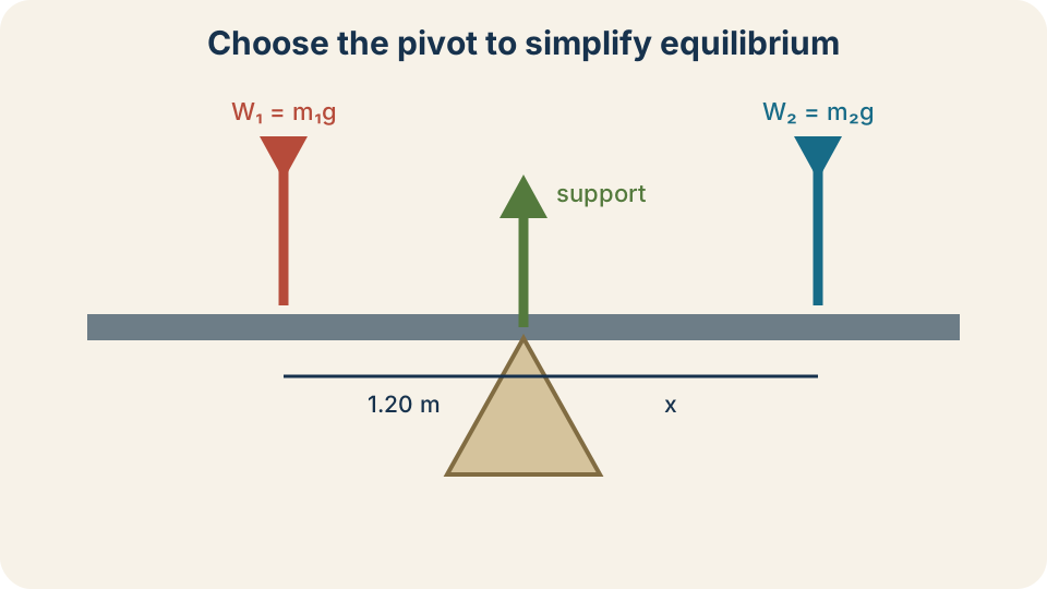
Choosing the support as the pivot removes the support force from the torque equation. The beam’s own weight also has zero moment arm because a uniform beam’s center of mass lies at the support. Each child’s weight acts downward at a measured horizontal distance. Opposite rotational tendencies receive opposite signs. Balance occurs when the signed torque sum equals zero. Force balance must still be checked separately.
Include an object’s own weight correctly
An extended object’s weight acts effectively at its center of mass in a uniform gravitational field. For a uniform rod, the center of mass lies at its geometric midpoint. If the pivot is not at that midpoint, the rod’s own weight produces torque. Omitting that contribution can change the predicted support force or balance point. A free-body diagram should include the object as well as attached loads.
Suppose a uniform horizontal beam of mass is hinged at its left end. Its center of mass is from the hinge. The weight is to three significant figures. Its torque magnitude about the hinge is . The direction is clockwise for a beam extending rightward.
If a cable supports the beam at an angle, only the cable force component perpendicular to the beam creates opposing torque. The hinge force still has zero torque about the hinge because its line of action passes through the pivot. Force equilibrium later determines the hinge components after cable tension is found from torque equilibrium. This order often simplifies the algebra. Strategic pivot choice and correct center-of-mass placement work together.
Connect net torque to angular acceleration
Torque becomes dynamical through for rotation about a fixed axis under suitable rigid-body conditions. The symbol is rotational inertia, which measures how mass is distributed relative to the axis. The symbol is angular acceleration in . Net torque plays a role analogous to net force in . Rotational inertia plays a role analogous to mass.
The analogy must not erase important differences. Rotational inertia depends on the chosen axis and the object’s mass distribution. Moving the same mass farther from the axis increases . A given net torque then produces a smaller angular acceleration. Torque depends on applied forces and geometry, while rotational inertia depends on the body and axis.
If net torque is zero, angular acceleration is zero, not necessarily angular velocity. A stationary object remains stationary, but an already rotating object can continue at constant angular velocity. This mirrors translational motion under zero net force. Static equilibrium adds the condition that the object is initially not rotating. Dynamic rotational equilibrium permits constant angular velocity.
Use a reliable solution workflow
First draw a free-body diagram and choose the system. Mark the pivot, every force, every application point, and the center of mass. Second choose a positive rotational direction. Third determine each perpendicular moment arm or perpendicular force component. Fourth calculate signed torques with units and sum them.
For equilibrium, set both the force and torque sums to zero. Choose a pivot that removes as many unknown forces as possible. Solve the torque equation before returning to force components when that order isolates an unknown cleanly. Check whether the result’s sign and position make physical sense. A predicted support point outside the actual beam may indicate impossible equilibrium or a sign error.
For dynamics, use the net signed torque rather than the sum of magnitudes. Pair it with rotational inertia about the same axis. Preserve radians and seconds in the angular-acceleration unit. Estimate direction before calculation so the final sign has meaning. A complete answer reports magnitude, direction, units, and the selected axis.
Repair common mistakes
One mistake is to use the full radius and full force without the sine factor when the vectors are not perpendicular. Use either , , or . Do not mix a perpendicular component with a perpendicular moment arm in the same product because that would apply the sine factor twice. Draw the right triangle that justifies the chosen form. Geometry should precede substitution.
Another mistake is to assign torque signs from force direction alone. Rotation depends on both position and force. Test the tendency by imagining the object free to rotate slightly about the pivot. Counterclockwise and clockwise contributions then become visually clear. Apply one sign convention consistently throughout the equation.
A third mistake is to label torque as energy because both share base dimensions. Use for torque and joules for energy. Another is to assume zero net force implies full equilibrium. Check the independent torque condition as well. These distinctions protect the physical meaning behind formally similar calculations.
Retrieve and extend
A perpendicular force applied from an axis produces of torque magnitude. Direction must be determined from the diagram or right-hand rule. A nonzero force produces zero torque when its line of action passes through the axis. In that case the perpendicular moment arm is zero. The force may still affect translation or internal loading.
Choosing a pivot through an unknown force removes that force’s torque term. This often allows another unknown to be found from rotational equilibrium before the force equations are used. The choice does not remove the force from the physical system. It only makes its moment arm zero about that axis. Torque calculations must always name or visibly identify the reference axis.
Torque links force geometry to rotational response. The vector definition explains direction, the sine factor selects perpendicular effectiveness, and the moment arm offers an equivalent geometric view. Signed sums distinguish balance from angular acceleration. The next lesson connects net torque with rotational inertia and angular acceleration in greater depth. Later, angular momentum will show how torque governs rotational change over time.