
When waves overlap in a linear medium, their disturbances add point by point. This rule is the principle of superposition. Interference is the pattern produced by that addition. The original waves do not ordinarily annihilate one another permanently when destructive interference occurs. They continue through the overlap region according to the governing wave equation.
The quantity that adds depends on the wave model. For a string, transverse displacement can add. For sound, pressure variation or particle displacement can add. For electromagnetic waves, electric and magnetic field components add. Energy and intensity generally do not add with the same simple signed rule because they depend on squared amplitudes and cross terms.
This lesson begins with pulses so addition can be seen directly. It then develops phase difference, sinusoidal addition, path difference, coherence, beats, and standing waves. Each formula is tied to a picture and a physical assumption. Worked examples retain units and distinguish local displacement from measured intensity. The goal is to predict a pattern and explain why it appears.
Learning objectives and an opening prediction
After this lesson, you should add overlapping disturbances at selected positions. You should distinguish constructive, destructive, and partial interference. You should translate among phase difference, path difference, and time delay. You should add equal-frequency sinusoids analytically. You should explain beats and standing-wave formation.
Imagine two upward pulses approaching one another on a stretched string. At complete overlap, the string displacement becomes the sum of their separate displacements. If both pulses are identical, the instantaneous amplitude doubles. After overlap, each pulse continues in its original direction in an ideal linear model. The event changes the observed shape temporarily rather than destroying pulse identity.
Now imagine one upward pulse and one equal downward pulse. At complete overlap, their displacements sum to zero. The string can be momentarily straight even though it is not permanently at rest. Different points can still possess velocity, and energy remains associated with the waves. Zero displacement at an instant is not the same as absence of motion or energy.
Superposition is a consequence of linearity
Suppose and each satisfy a linear wave equation. Then a weighted sum also satisfies it, where and are constants. For ordinary addition, choose . The net disturbance is . Addition occurs at the same position and time .
Linearity means the governing equation contains the disturbance and its derivatives only to the first power and does not multiply them together. A small-amplitude stretched string often approximates this condition. Sound in air at ordinary amplitudes is also often treated linearly. Very large amplitudes can produce nonlinear behavior such as shock formation or harmonic generation. Superposition then becomes approximate or fails.
The medium need not be motionless during overlap. Each wave contributes to the same physical variable. The measured result is one combined displacement, pressure, or field, not two separately colored substances. Decomposition into component waves is a mathematical representation. Many different decompositions can describe the same net pattern.
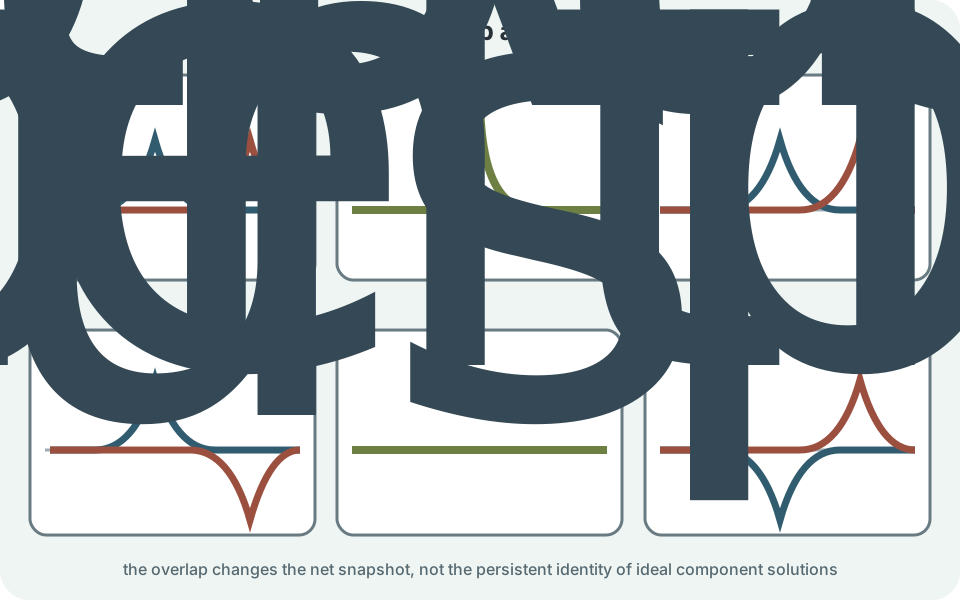
Add pulses point by point
To add pulse graphs, choose the same horizontal position on both component graphs. Read the signed displacement from the equilibrium line for each pulse. Add those signed values algebraically. Plot the sum at that position. Repeat across the overlap region.
If one pulse gives and another gives at a point, the net displacement is . If the second instead gives , the net is . The signs refer to the chosen transverse direction. They do not identify which wave is stronger in energy without additional information. The calculation must be repeated at other positions to construct the complete shape.
Outside the overlap region, only one pulse may contribute. There the net graph matches that pulse. Inside the overlap, shape can be larger, smaller, or more complicated than either component. The superposed shape must be constructed at one shared time. Adding graphs from different times produces no physical snapshot.
Constructive and destructive are limiting cases
Constructive interference occurs when component disturbances reinforce. Two positive displacements add positively, and two negative displacements add negatively. The magnitude of the net displacement exceeds either contribution when signs agree. Complete constructive interference of equal amplitudes doubles displacement amplitude. It does not automatically double intensity.
Destructive interference occurs when signs oppose. Complete cancellation requires equal magnitudes with opposite signs at the same position and time. Unequal opposing disturbances cancel only partially. A net amplitude can therefore lie anywhere between the difference and sum of component amplitudes. Most interference is partial rather than perfectly constructive or destructive.
These labels describe the net result at a chosen event or detector. A pair of sinusoidal waves can be constructive at one location and destructive at another because phase difference varies with position. Pulses can shift from reinforcement to cancellation as their shapes move through each other. Interference is spatiotemporal. A single label should not be attached to two waves without specifying where and when.
Phase locates a wave within its cycle
A sinusoidal traveling wave can be written . The amplitude is maximum displacement magnitude. The wave number is , where is wavelength. Angular frequency is , where is frequency. The constant is initial phase.
The entire cosine argument is phase. Two waves of equal frequency and wave number can differ by phase . A phase difference of or an integer multiple of means they are in phase. A difference of plus an integer multiple of means they are exactly out of phase. Intermediate values produce partial interference.
Radians are dimensionless, but labeling phase in radians communicates meaning. The product is dimensionless because has unit and has metres. The product is dimensionless because has and has seconds. Unit consistency checks the wave expression. Degrees may be used, but radians integrate naturally with calculus.
Add equal-frequency sinusoids
Consider and . Both waves have amplitude . They also share the same frequency because their phase variables differ only by constant . Add the two functions before calculating any intensity. A sum-to-product identity performs that addition. The resulting net displacement is shown below.
The net wave has the same frequency. Its signed amplitude factor is . Its phase lies halfway between the two component phases in this equal-amplitude case. The multiplier changes continuously as relative phase changes. This structure separates amplitude control from the continuing oscillation.
If , the amplitude factor is . If , the factor is zero because . If , the factor magnitude is . Phase therefore determines resultant amplitude continuously. Constructive and destructive interference are endpoints of that relationship.
When the cosine amplitude factor is negative, the net wave is equivalently shifted by phase . Amplitude is often reported as a nonnegative magnitude. Keep phase information when changing the sign convention. The identity assumes equal amplitudes and equal frequencies. Unequal amplitudes require vector or direct trigonometric addition.

Phasors organize sinusoidal addition
A phasor represents a sinusoid by a rotating vector in an abstract plane. Vector length represents amplitude, and vector angle represents phase. Equal-frequency phasors rotate together, so their relative angle remains constant. Their vector sum gives resultant amplitude and phase. Projection onto an axis recovers the physical sinusoid.
For amplitudes and separated by phase , the resultant magnitude satisfies . This is the law of cosines for vector addition. The symbol is resultant amplitude. When phase is zero, it becomes . When phase is , it becomes .
Phasors do not imply a string displacement literally rotates in another dimension. They are a mathematical representation of phase relationships. They are especially useful in acoustics, optics, and alternating-current circuits. The method requires common frequency for a fixed relative geometry. Different frequencies make the relative phasor angle change with time.
Path difference creates phase difference
Two waves traveling different distances can arrive with different phase. For equal wavelength , a path difference produces phase difference when source phases are equal and propagation occurs in the same medium. The symbol is one path length minus the other. Its sign can control phase direction. Interference intensity depends commonly on the cosine and may be insensitive to reversing that sign.
Constructive arrival occurs when for integer . The corresponding phase difference is . Destructive arrival for equal-amplitude waves occurs when . The phase difference is then an odd multiple of . These conditions assume no additional phase changes at reflection or source.
Reflections can add phase shifts. A transverse string wave reflecting from a fixed boundary reverses displacement, equivalent to a phase change of . Reflection from an ideal free boundary does not invert in the same way. Optical reflections can also acquire phase shifts depending on refractive-index change. Path difference alone is incomplete when boundary phase changes matter.
Worked path-difference example
Two coherent sound sources emit frequency in air where speed is . The wavelength is . Substitution gives . Units of reciprocal seconds cancel. The wavelength has metres.
At a detector, the path difference is . The ratio is . This equals . The phase difference is . Equal in-phase source amplitudes therefore arrive destructively.
If the source amplitudes are unequal, the detector does not reach zero amplitude. If reflections contribute, additional phases must be included. If the sources drift independently, the interference may vary with time. The simple answer depends on coherence and direct paths. Stating assumptions is part of the calculation.
Intensity includes an interference term
Wave intensity is proportional to the time average of a squared amplitude for many linear systems. Because the fields or displacements add first, squaring the sum creates a cross term. For two coherent contributions, a common form is . The quantities and are individual intensities. The cosine term is the interference contribution.
For equal intensities , complete constructive interference gives . The field or displacement amplitude doubles, and squaring produces four times one-wave intensity. Complete destructive interference gives zero under ideal equality. The average over all phases gives . Distinguish amplitude addition from intensity calculation.
Energy conservation is not violated by dark interference regions. Energy is redistributed spatially into bright or stronger regions. In a two-source pattern, integrating across the full appropriate region accounts for the supplied power. Local cancellation does not destroy energy. The sources and boundary conditions determine the complete flow.
Coherence stabilizes an interference pattern
Coherent sources maintain a predictable phase relationship over the observation time. They commonly share frequency and have sufficiently stable relative phase. Splitting one source into two paths is a reliable way to produce coherence. Two independent everyday light sources fluctuate too rapidly to form a stable visible pattern. Time averaging then removes the cross term.
Coherence has temporal and spatial aspects. Temporal coherence describes phase predictability over time or path difference and relates to spectral bandwidth. Spatial coherence describes phase correlation across different points of a wavefront. Real sources have finite coherence lengths and areas. An experiment must remain within those limits.
A detector also averages over finite time and area. Rapidly changing fringes can blur into uniform intensity. A large detector pixel can average bright and dark regions. Absence of a visible pattern does not prove waves failed to superpose. Measurement resolution and coherence determine observability.
Beats arise from nearby frequencies
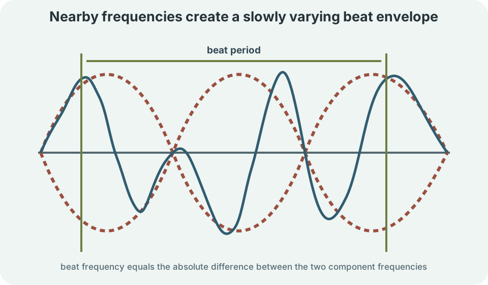
When two frequencies differ slightly, their phase difference changes slowly with time. Adding and gives a rapidly oscillating carrier multiplied by a slowly changing envelope. The angular frequencies are and . Their average sets the rapid oscillation scale. Their difference sets the slow modulation scale. For equal amplitudes, the relevant identity appears below.
The first cosine factor is the slowly varying envelope. The second cosine factor is the rapidly varying carrier. Their product grows and shrinks in magnitude. The envelope’s sign corresponds to a carrier phase reversal. The perceived or measured magnitude produces beats.
Beat frequency is . If tones have frequencies and , the beat frequency is . A listener hears about four loudness maxima per second under suitable conditions. The carrier frequency is near the average, . The ear responds to the changing amplitude envelope.
Beats are time-dependent interference rather than a stationary spatial fringe pattern. At some times the waves nearly reinforce, and half a beat later they nearly oppose. Exact cancellation requires equal amplitudes. Musicians use slowing beats to tune frequencies together. Instrument response and hearing limits affect perception.
Standing waves are persistent interference patterns
Two equal-frequency waves traveling in opposite directions can form a standing wave. Let and . Addition gives . Position and time factors separate. The pattern does not travel as a whole.
Nodes occur where in this chosen phase form. Those points remain at zero displacement. Antinodes occur where and oscillation amplitude is maximal. Adjacent nodes are separated by . Boundary conditions select allowed wavelengths.
A standing wave is not made of stationary matter. Medium particles oscillate except at nodes, and energy can exchange locally between forms. The traveling-wave components continue to carry the mathematical structure. Reflection commonly generates the counterpropagating wave. Resonance strengthens patterns compatible with the boundaries.
Superposition applies beyond mechanical waves
Sound waves superpose as pressure variations and particle motions. Noise-cancelling systems generate an approximately opposite pressure wave at a target region. Perfect cancellation everywhere is impossible for general three-dimensional fields and changing sources. Microphone position, delay, and frequency response matter. The engineering problem is spatiotemporal.
Electromagnetic fields also superpose in linear media. Optical interference adds electric-field amplitudes before intensity is calculated. Polarization matters because orthogonal field components may not create the same observable cross term. Detectors average optical oscillations while retaining slower spatial intensity structure. Field addition precedes energy detection.
Quantum probability amplitudes can interfere, but they are not ordinary material displacements. Complex amplitudes add, and probabilities follow from squared magnitude. The mathematical theme is linear combination. Interpretation depends on the theory. Similar equations do not erase physical distinctions.
Common mistakes and repairs
One mistake is adding intensities before considering coherence and phase. Add wave amplitudes or fields first. Then calculate the squared or averaged quantity measured. Include the cross term when phase remains correlated. If sources are incoherent over the measurement, justify why it averages away.
Another mistake is claiming destructive interference destroys the component waves. Track pulses before, during, and after overlap. In a linear medium, they emerge and continue. A momentarily zero displacement can coexist with nonzero velocity and energy. Distinguish the net observation from component decomposition.
A third mistake is using path-difference conditions without checking reflection or source phase. Write total phase difference as propagation contribution plus any initial and boundary phase changes. State whether sources begin in phase. Use the wavelength in the actual medium. Conditions are only as complete as the phase account.
A reliable interference workflow
First identify the physical quantity that superposes. State whether it is displacement, pressure variation, electric field, or another signed amplitude. Confirm the linear approximation. Write each contribution at the same position and time. Preserve signs and vector components.
Second determine phase relationships. Use direct phase values, time delay, or with boundary corrections. Add equal-frequency waves by identities or phasors. For pulses, add graphs point by point. For unequal frequencies, expect a time-varying phase and beats.
Third connect amplitude to what a detector measures. Square and average when intensity requires it. Check coherence, detector resolution, and finite bandwidth. Test limiting cases of zero and phase difference. Explain where energy is redistributed.
Retrieval practice and synthesis
Without looking back, explain why two equal opposite pulses can produce zero displacement at one instant yet later reappear. Use superposition and linearity. Distinguish displacement from energy. State what a sequence of snapshots would show. Identify one condition under which the ideal result could fail.
Derive the resultant amplitude for two equal-frequency equal-amplitude sinusoids separated by phase . Evaluate the result at , , and . Describe each case in words. Explain why intensity at complete reinforcement is four times one-wave intensity rather than twice. Keep amplitude and intensity conceptually separate.
Compare beats and standing waves. Beats arise from nearby frequencies and produce a time-varying envelope. Standing waves arise from equal-frequency counterpropagating components and produce fixed nodes. Both follow superposition. Their distinct phase relationships create different observations.