
Light can brighten one location and darken another even when two beams overlap there. This behavior follows from superposition: electromagnetic field amplitudes add before intensity is calculated. In-phase waves reinforce, while out-of-phase waves can cancel. Diffraction is the spreading and interference produced when a wave encounters an aperture or obstacle. Both effects reveal the wave character of light.
Fringe formulas are meaningful only after geometry and phase are understood. Path difference tells how much farther one wave travels than another. Dividing that difference by wavelength determines relative phase. Bright and dark conditions depend on whether the waves arrive aligned or opposed. Screen distance and slit spacing then convert angle into position.
This lesson begins with wave addition and coherence. It develops two-source interference, derives double-slit positions, and then treats every point across one slit as a source of diffraction. A diffraction grating will extend the idea to many slits. Resolution and wavelength measurement will connect the patterns to instruments. Model limitations will keep small-angle and far-field approximations visible.
Learning objectives and an opening prediction
After this lesson, you should add wave amplitudes and distinguish amplitude from intensity. You should translate path difference into constructive or destructive interference. You should calculate double-slit fringe angles and positions. You should identify single-slit minima and explain the broad central maximum. You should also analyze gratings, coherence, resolution, and approximation limits.
Imagine water waves passing through two narrow openings. At a point where both crests arrive together, predict the displacement. Their amplitudes add and produce constructive interference. Where a crest arrives with an equal trough, amplitudes cancel and produce destructive interference. Energy is redistributed across the pattern rather than destroyed at every dark location.
Now make each opening narrower. The emerging waves spread through a larger angular range. Narrow apertures diffract more strongly when their width approaches wavelength. A very wide aperture compared with wavelength produces only small angular spreading. The ratio of wavelength to aperture scale controls the effect.
Superposition adds fields, not intensities first
The superposition principle states that the total wave displacement or field equals the sum of individual fields. For two electric-field components, . The signs and phases of the fields matter. Equal positive amplitudes double the instantaneous field. Equal opposite amplitudes cancel at that instant.
Optical intensity is proportional to the time average of the squared electric-field amplitude, . Therefore doubling coherent field amplitude can produce four times the single-wave intensity at a constructive maximum. At a destructive minimum, equal fields can produce ideal zero intensity. One must add fields first and square afterward. Adding isolated intensities would miss interference cross terms.
Interference does not violate energy conservation. Bright regions receive more energy flux while dark regions receive less. Integrated across a complete appropriate pattern, energy matches the supplied wave energy after accounting for reflection, absorption, and geometry. The pattern redirects energy. Cancellation at one location is accompanied by reinforcement elsewhere.
Phase and path difference
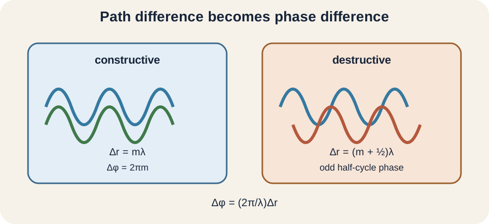
A sinusoidal wave repeats phase every wavelength . If one path exceeds another by , the corresponding phase difference is . The Greek capital delta indicates a difference, and denotes phase in radians. A path difference of one wavelength gives radians. A half-wavelength gives radians.
Constructive interference occurs when for integer . These path differences correspond to whole cycles and phase differences . Destructive interference for two equal in-phase sources occurs when . These correspond to odd half-cycles. Initial source phase can shift both conditions.
The integer is called order. The central constructive maximum has . Positive and negative orders lie on opposite sides of the center in a symmetric setup. Order is dimensionless. It should not be confused with the number of slits or wavelength count along one path.
Coherence makes stable fringes possible
Two waves are coherent when their relative phase remains sufficiently stable during observation. The same frequency is necessary for a stationary simple pattern, but phase stability is also required. Two independent ordinary lamps fluctuate independently and usually do not produce visible stable fringes. Splitting one source creates related wave paths. Lasers often provide strong temporal and spatial coherence.
Temporal coherence concerns phase predictability over time and path-length difference. A source with a narrow frequency range has a longer coherence time and length. If path difference exceeds coherence length, phase relationships wash out. Spatial coherence concerns correlation across different source points. A small or well-collimated source improves it.
Perfect coherence is an idealization. Finite bandwidth, vibration, air currents, detector integration, and source size reduce fringe visibility. Visibility can be quantified by . The symbol is dimensionless and lies between zero and one under ordinary conditions. Unequal slit intensities also prevent complete dark cancellation.
Two-slit geometry produces a path difference
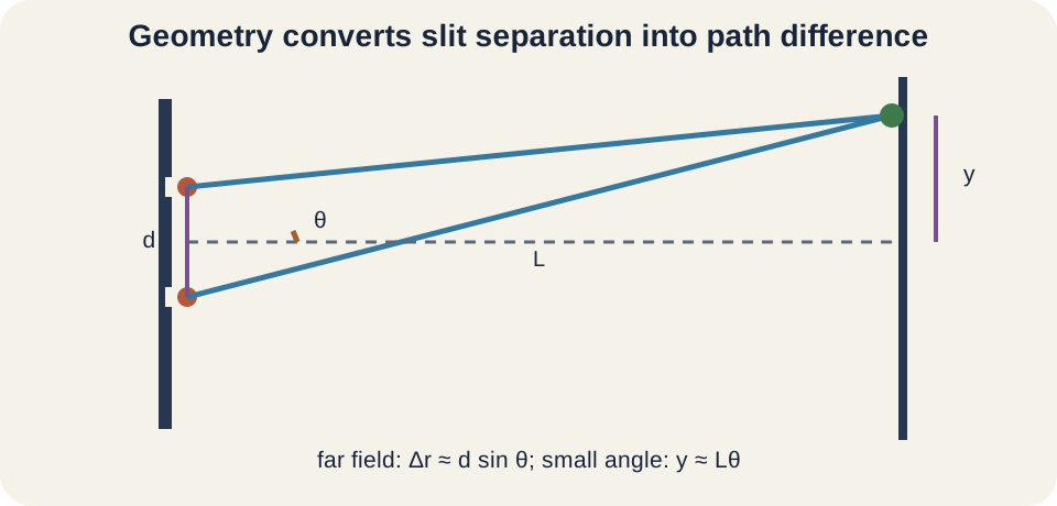
Two narrow slits separated by center-to-center distance illuminate a distant screen. Observe at angle from the central perpendicular axis. In the far-field geometry, the path difference is approximately . The slit separation and path difference share length units. The sine is dimensionless.
Constructive directions satisfy . Destructive directions satisfy for equal in-phase slit sources. A real angle requires . Therefore only finitely many orders can exist for a given separation. A missing mathematical solution is a physical constraint, not a calculator error.
The central point has equal path lengths and , so it is constructive for in-phase slits. Moving across the screen changes the path difference continuously. Each added wavelength produces the next bright order. Symmetry gives equal positive and negative angles. The pattern is angular before it is converted to screen position.
Screen positions use an additional approximation
If the screen is distance from the slits and a fringe is transverse distance from center, geometry gives . This relation is exact for a flat screen within the ray geometry. For small angles measured in radians, . Then . The approximation makes bright fringes evenly spaced.
Adjacent bright-fringe spacing is . Larger wavelength or screen distance increases spacing. Larger slit separation decreases spacing. These trends can be checked without calculation. The same relation can solve for an unknown wavelength or slit separation.
The small-angle approximation fails for large or high orders. Then use and without replacing the trigonometric functions. Even exact trigonometry still assumes sufficiently distant observation for the simple path-difference geometry. Approximation layers should be removed one at a time. A formula’s compactness hides its conditions.
Worked double-slit example
Light with wavelength illuminates slits separated by . A screen is away. Convert wavelength to and separation to . The approximate fringe spacing is . Compatible meter units are required.
Substitution gives . One meter cancels through the denominator, leaving a screen distance. The first-order maxima lie about from center. The central maximum is assigned position zero. The second orders lie about under the approximation.
Check the first angle: , so . Since the angle is small, is justified. The ratio is also approximately . If the ratio were not small, exact tangent conversion would be needed. Numerical checking validates the approximation rather than assuming it.
Single-slit diffraction arises within one aperture
A slit of finite width can be treated using Huygens–Fresnel reasoning. Every point across the aperture contributes a wavelet. At the central direction, contributions arrive in phase and reinforce. Away from center, phase varies continuously across the slit. At certain angles, contributions cancel pairwise.
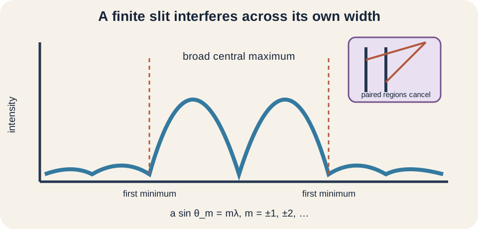
Single-slit minima satisfy for . There is no minimum because the center is the principal maximum. The first minima occur at . Narrower slit width produces larger diffraction angles. This relation differs from the double-slit bright condition despite similar symbols.
The central maximum lies between the first negative and positive minima. Its angular width is approximately for small angles. It is about twice the width of each neighboring maximum in the common far-field pattern. Side maxima become weaker away from center. A real intensity curve contains a broad envelope, not equal bright bars.
Why a single slit can self-interfere
At the first minimum, divide the slit into two equal halves. Pair a point in the upper half with a point half a slit-width below it. Their path difference toward the observation angle is . When , each pair differs by and cancels. All pairs across the slit then cancel ideally.
For the second minimum, the aperture can be divided into four paired regions. The general integral of contributions gives the full intensity form. Elementary pair arguments identify minima but do not calculate every side-maximum position exactly. They also assume uniform illumination across the slit. An aperture with a different amplitude profile gives a different pattern.
The language “the wave interferes with itself” means different spatial portions of one coherent wavefront contribute to the same observation point. It does not imply a photon is literally cut into classical fragments. Quantum descriptions also predict the same probability distribution one detection at a time. The accumulated pattern follows wave amplitudes. Interpretation and calculation should not be conflated.
Finite slit width modulates double-slit fringes
Real double slits have both separation and individual width . The two-slit interference creates closely spaced fringes. Each slit also produces a broad single-slit diffraction envelope. The observed intensity is the interference pattern multiplied by the diffraction envelope. Fringes become weaker toward envelope minima.
If a double-slit maximum coincides with a single-slit minimum, that bright order disappears. Double-slit maxima satisfy , while single-slit minima satisfy . Coincidence occurs when . These missing orders provide information about the width-to-separation ratio. A two-slit pattern is therefore not truly uniform across an unlimited screen.
Treating slits as infinitesimally narrow omits the envelope. That approximation may be adequate near the center when slit width is very small. High-quality experimental interpretation should plot intensity rather than only mark bright and dark positions. Detector dynamic range matters because weak side fringes may fall below visibility. Absence on a photograph is not always an exact theoretical zero.
Diffraction gratings sharpen wavelength separation
A diffraction grating contains many equally spaced slits or grooves. Principal maxima satisfy , the same angular condition as two-slit constructive interference. With many sources, off-condition amplitudes cancel more completely. Principal maxima become narrower and brighter. This sharpness improves angular discrimination.
Grating spacing may be obtained from line density. A grating with has . Units must be inverted carefully. Higher line density means smaller spacing. Smaller produces larger angular separation for a given wavelength and order.
Different wavelengths satisfy the condition at different angles, so a grating disperses a spectrum. Higher orders give greater angular separation but may overlap wavelengths from other orders. Only orders with exist. Grating efficiency also depends on groove shape and wavelength. Spectrometer design balances range, resolution, brightness, and order overlap.
Diffraction limits imaging resolution
A circular aperture does not focus a point source to an infinitesimal point. Diffraction produces an Airy pattern with a central disk and rings. The first dark angular radius is approximately for small angles, where is aperture diameter. Larger aperture reduces the diffraction angle. Shorter wavelength also improves ideal resolution.
The Rayleigh criterion says two equal point sources are just resolved when one Airy maximum aligns approximately with the other’s first minimum. The corresponding angular separation is . This is a convention for practical distinction, not an absolute law forbidding all inference below it. Signal processing, noise, prior information, and detector sampling affect real resolution. Diffraction provides a fundamental optical scale.
Telescopes use large apertures partly to improve angular resolution and collect more light. Microscopes use short wavelengths and high numerical aperture. A pinhole made indefinitely small does not yield indefinitely sharp imaging because diffraction spreading grows. Geometric blur and diffraction blur trade against each other. Optical design finds a useful balance.
Wavelength, aperture, and everyday visibility
Sound waves diffract strongly around doorways because their wavelengths can be comparable to doorway dimensions. Visible-light wavelengths are hundreds of nanometers, much smaller than ordinary doors, so light diffraction around them is tiny. This explains why sound can be heard around a corner while sharp light shadows remain common. The same wave principle applies. Scale ratio determines visibility.
Radio waves with long wavelengths can bend around terrain and buildings more than short optical waves. Water waves spread after passing through a narrow harbor opening. X-rays diffract from atomic-scale crystal spacings, enabling structural measurement. Electron matter waves also diffract from crystals. Diffraction is not exclusive to light.
Aperture size alone is not enough to predict spreading. One must compare it with wavelength. A opening is enormous for visible light but small for a centimeter radio wave. Dimensionless ratio organizes regimes. Similar ratios produce similar angular behavior under comparable geometry.
Experimental measurement and uncertainty
A double-slit experiment can estimate wavelength from . Measure several fringe spacings across a wide span rather than one adjacent pair. If ten intervals span distance , use . This reduces fractional ruler uncertainty. Measure between matching bright centers consistently.
Slit separation and screen distance also have uncertainty. Misalignment can shift the center and alter effective geometry. A broad source, vibration, or ambient light reduces contrast. A camera can saturate bright maxima and distort widths. Record instrument resolution and repeat trials.
Plot fringe order against position . Under the small-angle model, slope is if position is vertical and order horizontal, or its reciprocal if axes reverse. A fitted line uses all measured orders. Residual curvature can reveal breakdown of the small-angle approximation. Graph orientation again determines slope meaning.
Common misconceptions and repairs
One misconception adds light intensities before considering phase. Coherent field amplitudes add, then the squared result determines intensity. Independent incoherent sources often allow intensity addition because phase cross terms average away. The distinction depends on coherence. State the source relationship.
Another misconception says diffraction occurs only at a slit edge. Contributions across the entire aperture interfere in the far field. Edges define the allowed region, but the pattern depends on its full shape and illumination. A circular aperture and rectangular slit produce different distributions. Aperture geometry is encoded in the pattern.
A third misconception uses without identifying whether is slit separation or width and whether the condition marks maxima or minima. For double-slit or grating interference, commonly means separation and integer orders mark maxima. For single-slit diffraction, commonly means width and nonzero integers mark minima. Label the physical length beside the equation. Similar algebra can describe different features.
Practice with guided feedback
First, find double-slit fringe spacing for , , and . Second, find the first single-slit minimum angle for at the same wavelength. Third, explain why stable fringes require coherence. Fourth, predict how narrowing the slit changes central-maximum width. Convert all lengths to meters.
Fringe spacing is . For the single slit, , so . Coherence keeps relative phase stable during measurement. Narrowing increases and broadens the central maximum. Every result matches the expected scaling trend.
For a pattern check, distinguish the fine fringe spacing from the broad envelope width. Mark the central order and symmetric positive and negative orders. Verify that no requested order requires sine magnitude above one. State whether small-angle approximation was used. These checks make a diagram part of the solution.
Retrieval and connection forward
Without looking back, explain why fields add before intensities. Convert a path difference into phase difference. Derive the double-slit bright condition and approximate screen spacing. Explain the single-slit first minimum with paired aperture regions. Finish by comparing two slits, many-slit gratings, and circular-aperture resolution.
Lens lessons use diffraction to explain why ideal ray focusing has finite resolution. Quantum lessons show single photons accumulating an interference probability pattern. Spectroscopy uses gratings to separate wavelengths. Crystallography uses wavelength-scale spacing to infer structure. Fourier methods will generalize aperture shape into far-field patterns.
Keep one organizing statement: interference follows superposition of coherent amplitudes, and path difference sets relative phase. Diffraction is interference produced by a finite aperture or obstacle. Two slits create periodic fringes, one slit creates an envelope, and many slits sharpen principal maxima. Wavelength-to-aperture scale controls spreading. Geometry, coherence, and approximation limits determine whether the formulas describe the experiment.