
A mirror redirects light by reflection, while a lens redirects it by refraction at two surfaces. Carefully shaped elements can make rays from one object point converge or appear to diverge from a corresponding image point. The image can be projected onto a screen or exist only as a virtual reconstruction. Ray diagrams reveal this geometry. Equations quantify it when their sign convention is applied consistently.
Optical vocabulary is easy to memorize and easy to misuse. Real and virtual describe ray convergence, not whether an image can be seen. Upright and inverted describe orientation relative to the object. Magnified and reduced describe size. An image can be virtual, upright, and magnified at the same time.
This lesson begins with the principal axis, focal point, and three useful rays. It then defines one explicit real-is-positive sign convention before applying the thin lens and spherical mirror equation. Worked cases will compare diagrams with calculations. Optical power, multiple elements, and aberrations will extend the ideal model. Every numerical distance will include units and interpretation.
Learning objectives and an opening prediction
After this lesson, you should draw principal rays for converging and diverging lenses and mirrors. You should classify images as real or virtual, upright or inverted, and enlarged or reduced. You should use with a declared sign convention. You should calculate transverse magnification. You should also explain optical power, multiple-element imaging, and ideal-model limitations.
Imagine holding a converging lens above printed text and moving it close to the page. Predict the image. When the object lies inside the focal length, emerging rays diverge but appear to originate from a larger upright virtual image. Moving the lens farther can place the object beyond the focal point. The image can then become real and inverted.
Now consider a plane mirror. Rays do not physically travel behind it, yet an observer sees an image there. Backward extensions of reflected rays intersect behind the surface. That virtual image cannot be caught on a screen at its apparent location. It remains visible because reflected rays enter the eye.
Establish the optical geometry
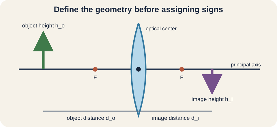
The principal axis is the line through an ideal element’s center of symmetry. Object height is drawn perpendicular to it. The optical center of a thin lens lies where a central ray is approximated as undeviated. A spherical mirror has a vertex where the axis meets the surface. Distances are measured along the axis.
The focal point is where rays initially parallel to the axis converge or appear to diverge from after interacting with the element. A converging element has a real focal point on the outgoing side for parallel incident light. A diverging element has a virtual focal point on the incident side. Focal length is the signed distance from the element to that point. Its magnitude measures focusing strength.
Thin-lens and paraxial-ray models assume element thickness is small relative to relevant distances and rays stay close to the axis with modest angles. Under these assumptions, one focal length describes the element. Real lenses have two principal planes and wavelength-dependent focal properties. Spherical mirrors also deviate for far-axis rays. The ideal geometry is a controlled approximation.
Real and virtual images follow ray behavior
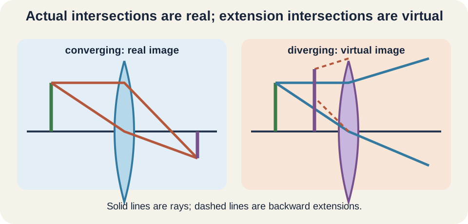
A real image forms where outgoing rays physically converge. Placing a screen at that location can intercept the light pattern. The rays continue after crossing, so an observer can also view the image. Real images from a single converging thin lens or concave mirror are commonly inverted. Their image distance is positive in the convention used here.
A virtual image forms where outgoing rays do not actually converge but their backward extensions meet. A screen placed at the apparent point receives no focused pattern from those extensions. The eye can still interpret diverging rays as coming from that location. Plane mirrors, diverging lenses, convex mirrors, and magnifiers commonly form virtual images. Their image distance is negative in this convention.
“Virtual” does not mean imaginary or invisible. It specifies the geometry of actual rays versus their extensions. A photograph of a plane-mirror image records real light that reflected from the mirror into the camera. The camera lens then forms its own real image on the sensor. Multiple stages can involve both virtual and real intermediate objects.
Principal rays for a converging lens
Three principal rays make a thin converging-lens diagram efficient. A ray from the object parallel to the axis refracts through the far focal point. A ray through the near focal point emerges parallel to the axis. A ray through the optical center continues approximately straight. Any two correctly drawn rays locate the ideal image.
If the object lies beyond twice the focal length, the image forms between and , real, inverted, and reduced. At , the ideal image lies at with equal magnitude size. Between and , the image lies beyond , real, inverted, and magnified. At the focal plane, emerging rays are parallel and the finite image distance diverges. Inside , the image is virtual, upright, and magnified.
These cases should be reasoned from rays rather than memorized as disconnected rows. Move the object toward the focal point from far away and watch the intersection move farther away. Crossing inside the focal point makes actual outgoing rays diverge. Their backward extensions meet on the object side. The algebra will reproduce the same transition.
Principal rays for a diverging lens
A thin diverging lens spreads a ray initially parallel to the axis as if it came from the near focal point. A ray directed toward the far focal point emerges parallel to the axis. A central ray continues approximately straight. The actual outgoing rays diverge. Their backward extensions intersect on the object side.
For a real object, a single diverging lens forms a virtual, upright, reduced image between the lens and its near focal point. This classification remains stable as ordinary object distance changes. The image approaches the lens when the object approaches. It approaches the focal region as the object moves very far away. The signed focal length is negative.
The image can serve as an object for another element. If a second lens intercepts the rays, the intermediate virtual image location determines its object distance. Compound optical systems therefore require stage-by-stage analysis. One element’s output becomes the next element’s input. Global labels must not replace local distances.
Concave mirrors converge reflected rays
A concave spherical mirror curves inward toward the object side. Its focal point lies in front of the mirror and is real for parallel incident rays. In the paraxial approximation, focal length is , where is radius of curvature. The center of curvature lies at distance . Both and are positive in the convention used here.
A ray parallel to the axis reflects through the focal point. A ray through the focal point reflects parallel to the axis. A ray directed through the center of curvature returns along its incoming path because it strikes normally. These principal rays locate the image. Their reflection obeys equal angles relative to the local surface normal.
Concave-mirror image cases parallel those of a converging lens. Objects beyond the focal point produce real inverted images, with size depending on distance. An object inside the focal length produces a virtual upright magnified image behind the mirror. Makeup and shaving mirrors exploit this near-object case. Telescopes often use concave mirrors to form real images of distant objects.
Convex and plane mirrors
A convex mirror bulges toward the object and diverges reflected rays. A ray parallel to the axis reflects as if it came from the focal point behind the mirror. Backward extensions meet behind the surface. For a real object, the image is virtual, upright, and reduced. The focal length is negative in this convention.
Wide fields of view make convex mirrors useful for vehicle and security applications. Reduced images fit more angular scene into a limited mirror area. The warning that objects appear closer than they are reflects altered size and angular cues. The mirror does not change the object’s physical position. Perception reconstructs location from diverging rays.
A plane mirror is the limiting case with infinite radius and infinite focal length. Its image distance magnitude equals object distance, and magnification is . The image is virtual, upright, and equal in size. “Left-right reversal” is better understood as front-back reversal across the mirror plane. Coordinates perpendicular to the mirror change sign.
Choose and state a sign convention
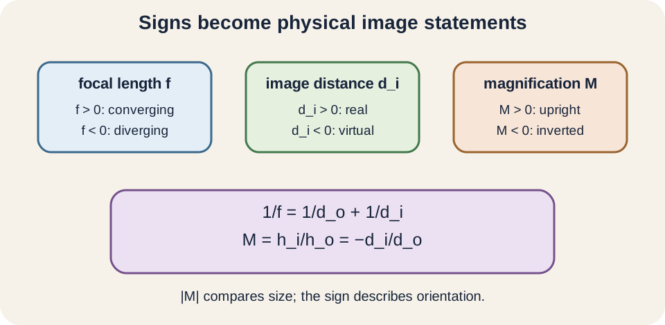
This lesson uses the real-is-positive convention for a single element. Real object distance is positive. Real image distance is positive, while virtual image distance is negative. Converging focal length is positive and diverging focal length is negative. Object height is positive when upright relative to the chosen transverse axis.
Other textbooks may use a Cartesian convention based on propagation direction. Both can work if used consistently. Never combine a distance sign from one convention with an equation interpretation from another. State the convention before substituting. A ray diagram provides an independent check on signs.
Distances in the equation refer to the element’s reference plane or vertex under the thin-element approximation. They are not arbitrary separations between object and image. A negative number is not an impossible length. It encodes a virtual location on the designated side. Words must accompany the signed result.
The thin-element equation
For a thin lens or paraxial spherical mirror under this convention, . All three quantities must use the same length unit. Reciprocals therefore have inverse-length units. One may rearrange to . Solve the reciprocal before inverting.
Combining fractions gives when neither denominator creates a singular case. This form makes the focal transition visible. For a converging element with , the denominator is positive and is real. For , the denominator is negative and is virtual. At , the ideal image is at infinity.
The equation locates an image but does not by itself show all ray paths. A numerical result can be sign-correct yet based on a mistaken diagram or element type. Predict the image category first. Calculate second. Compare the sign and scale with the prediction.
Magnification connects size and orientation
Transverse magnification is . The symbol is object height and is signed image height. Magnification is dimensionless because like length units cancel. A negative means inverted image. A positive means upright image.
The magnitude describes size ratio. If , the image is enlarged. If , it is reduced. If , object and image heights have equal magnitudes. Sign and magnitude answer different classification questions.
Suppose and object height is . Then . The image is inverted and times as tall. Its negative height is an orientation coordinate, not a negative physical size. The physical height magnitude is .
Worked converging-lens example
A converging lens has and a real object at . Predict a real inverted reduced image because the object lies beyond . Use . The difference is . Therefore .
The positive image distance confirms a real image on the outgoing side. Magnification is . The negative sign means inverted and magnitude one half means reduced. A ray diagram should place the image between and . All classifications agree.
If object height is , image height is . The screen should be placed from the lens. Moving it elsewhere produces blur rather than a sharply focused image. The negative height agrees with the inverted ray diagram. Finite aperture and aberrations still limit perfect sharpness.
Worked virtual-image example
Use the same converging lens with an object at , inside the focal length. Predict a virtual upright enlarged image. The equation gives . Therefore . The negative sign places the image on the object side.
Magnification is . The positive sign confirms upright orientation. Its magnitude confirms enlargement. This is the operating principle of a simple magnifier. The eye sees rays that appear to originate from the virtual image.
No screen at on the object side can capture the virtual image directly because no outgoing rays converge there. A camera or eye can still form a later real image on its detector or retina. Image classification is local to the element under analysis. The negative distance describes the ray-extension location. Optical systems often transform virtual objects into real images at later stages.
Worked convex-mirror example
A convex mirror has and a real object at . Then . Thus . The image lies behind the mirror and is virtual. This matches the ray prediction.
Magnification is . The image is upright and one quarter the object’s height. It lies between mirror and focal point because . The broad field of view comes with reduced angular image size. Signs encode all three facts.
A sign error making positive would predict a different optical element. Memorizing equations without element classification causes that error. Label the mirror as diverging before assigning . Draw one principal ray. Then calculate.
Optical power measures convergence strength
Optical power is when focal length is measured in meters. Its unit is the diopter, . A converging lens has positive power, while a diverging lens has negative power. Short focal length means large power magnitude. Optical power is not energy per time.
A lens with has . A lens with has . The signs indicate convergence or divergence. Eyeglass prescriptions use diopters. Additional notation can describe astigmatic correction.
For thin lenses in contact under the surrounding-medium approximation, powers add: . Equivalently, . Positive and negative powers can partially cancel. Separation between lenses requires a more complete relation. Contact addition is an ideal special case.
Multiple optical elements require stages
In a two-lens system, solve the first lens image completely. That image becomes the object for the second lens. Its object distance is measured from the second lens using the same local sign convention. The intermediate image may be real or virtual. Geometry determines the new sign.
Suppose lens one forms a real image to the right, but lens two sits before that convergence point. Rays arriving at lens two are already converging toward a point on its outgoing side. That point acts as a virtual object for lens two. The second object distance is negative under real-is-positive convention. A sketch prevents mistaken subtraction. Distances must be measured from the correct element.
Total transverse magnification is the product . Two inversions produce a positive upright final orientation relative to the original. Size ratios multiply. Telescopes, microscopes, cameras, and eyes use multiple stages. Matrix optics provides a systematic later method.
The human eye and corrective lenses
The eye’s cornea and lens refract light to form a real inverted image on the retina. Neural processing supports visual perception; the retina does not need an upright projected image. Accommodation changes lens shape to focus objects at different distances. The far point and near point describe focusing range. Age and optical conditions change these limits.
Myopia causes distant parallel rays to focus before the retina under a simplified model. A diverging corrective lens reduces convergence so the eye focuses on the retina. Hyperopia or some presbyopic near-vision needs can use converging correction. Prescription power depends on the desired object-image relationship and lens placement. Human vision is more complex than one thin lens.
Astigmatism involves different focusing power in different meridians. Cylindrical correction addresses that directional difference. Chromatic and higher-order aberrations also affect image quality. Medical diagnosis and prescription belong to trained professionals. The elementary model explains optical principles, not individual care.
Aberrations reveal ideal-model limits
Spherical aberration occurs because rays far from the axis do not focus at exactly the paraxial focal point for spherical surfaces. Restricting aperture reduces the effect but also reduces light and increases diffraction. Aspheric surfaces can improve focusing. The ideal principal rays represent near-axis behavior. They do not guarantee one exact focus for every ray.
Chromatic aberration occurs because refractive index depends on wavelength. A simple lens therefore has different focal lengths for different colors. Compound achromatic lenses combine materials and powers to reduce the separation. Mirrors avoid ordinary refractive chromatic aberration because reflection geometry is less wavelength-dependent. Coatings and detectors introduce other spectral effects.
Coma, astigmatism, field curvature, and distortion affect off-axis imaging. Aperture diffraction also limits resolution even in a perfectly corrected system. Manufacturing tolerances and alignment matter. Image quality is therefore not captured by focal length alone. Optical engineering balances many error sources.
Common misconceptions and repairs
One misconception says a virtual image cannot be seen. It cannot be projected at its apparent location, but rays entering an eye or camera can still carry it. Plane mirrors provide daily evidence. Distinguish screen formation from visual detection. Use ray convergence as the definition.
Another misconception uses negative image distance to mean a calculation failed. Under this convention, it indicates a virtual image. Negative focal length indicates a diverging element. Negative magnification indicates inversion. Each sign has a defined geometric meaning.
A third misconception draws rays bending only at a lens center while using principal rules inconsistently. The thin lens is represented by an effective plane for ray construction. Parallel, focal, and central rays must follow their specific rules. Two rays from the same object point should meet or have backward extensions meet. A third ray checks the construction.
Practice with guided feedback
First, a converging lens has and ; find and . Second, classify the image. Third, repeat classification qualitatively if the object moves to . Fourth, explain why a diverging lens with a real object normally gives negative . Predict before calculating.
For the first case, , so . Magnification is . The image is real, inverted, and reduced. At , the converging lens forms a virtual upright enlarged image. A diverging lens sends actual rays apart, so their backward extensions meet on the object side and .
For a diagram check, locate both focal points and draw two principal rays. For a sign check, compare actual convergence with the sign of . For a scale check, compare with the ray-drawn image height. For a unit check, use one length unit throughout. Agreement across representations validates the solution.
Retrieval and connection forward
Without looking back, define real and virtual images through actual rays. Draw principal rays for each lens type and mirror type. State the sign convention and thin-element equation. Explain magnification sign and magnitude. Finish by solving one case and verifying its classification with a ray diagram.
Diffraction will set the resolution limit absent from ideal ray diagrams. Interference explains antireflection coatings and wavelength-dependent effects. Wavefront methods derive focusing more fundamentally. Matrix optics handles multiple paraxial elements efficiently. Cameras, telescopes, microscopes, and eyes combine these concepts.
Keep one organizing statement: lenses refract and mirrors reflect rays so that actual rays or backward extensions define an image. Ray diagrams predict location and classification, while the thin-element equation quantifies distance under a declared convention. Magnification separates orientation sign from size magnitude. Real elements add thickness, dispersion, aberration, alignment, and diffraction. A calculation is complete only when its signs become a physical image description.