
Light changes direction when it meets a boundary. Some energy usually returns to the original medium as reflection, while some enters the second medium as transmission. If wave speed differs between the media, the transmitted direction generally changes through refraction. Geometric optics represents propagation using rays perpendicular to wavefronts. This model works when relevant structures are large compared with wavelength.
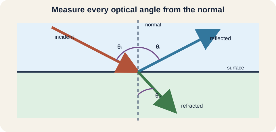
The surface normal is the central geometric reference. It is an imaginary line perpendicular to the boundary at the point where the ray arrives. Optical incidence, reflection, and refraction angles are measured from this normal, not from the surface. Measuring from the wrong line produces complementary angles and incorrect results. A labeled normal should be the first mark on every boundary diagram.
This lesson connects ray rules with their wave meaning. Reflection will follow equal angles, refraction will follow Snell’s law, and wavelength change will follow . Critical angle and total internal reflection will emerge from the allowed range of the sine function. Worked examples will include units and inverse-trigonometric reasoning. Real boundaries will then reveal polarization, dispersion, absorption, and model limitations.
Learning objectives and an opening prediction
After this lesson, you should construct a normal and measure all optical angles from it. You should apply the law of reflection and Snell’s law. You should relate refractive index to speed and wavelength while preserving frequency across a stationary boundary. You should calculate a critical angle and state when total internal reflection is possible. You should also interpret apparent depth and recognize limits of ray optics.
Imagine a ray traveling from air into glass at an oblique angle. Predict whether it bends toward or away from the normal. Glass usually has a larger refractive index and lower light speed than air. The ray bends toward the normal. Its frequency remains fixed, while its wavelength becomes shorter.
Now reverse the direction so light travels from glass into air. The ray bends away from the normal for angles that permit transmission. At sufficiently large incidence angle, Snell’s law would demand a transmitted sine greater than one. No propagating transmitted ray then exists in the ideal model, producing total internal reflection. Direction and index ordering determine whether that phenomenon is possible.
Rays, wavefronts, and the normal
A ray is an ideal line showing the local propagation direction of light energy in geometric optics. A wavefront joins points with equal phase. In an isotropic medium, rays are perpendicular to wavefronts. Parallel rays represent a locally plane wave. Diverging rays can represent light spreading from a point source.
At a smooth boundary, draw the normal through the point of incidence. The incident ray approaches the boundary, the reflected ray leaves within the first medium, and the refracted ray enters the second. The incidence angle is , reflection angle is , and transmission angle is often or . Each angle lies between a ray and the normal. Subscripts label roles rather than multiplication.
At normal incidence, . The transmitted ray does not change direction even if its speed changes because there is no preferred sideways direction. Reflection may still occur. Thus “no bending” does not imply identical media. Direction, speed, and energy partition are separate questions.
The law of reflection
The law of reflection is . Incident ray, reflected ray, and normal lie in one plane for a flat isotropic boundary. The equality uses angles from the normal. It holds for smooth mirror-like reflection under geometric optics. It does not say reflected intensity equals incident intensity.
Reflection can be understood through wavefront timing. Different parts of an oblique wavefront reach the boundary at different times. The reflected wavefront geometry must preserve phase continuity along the boundary. This construction produces equal incidence and reflection angles. Fermat’s principle of stationary travel time gives the same result.
Specular reflection occurs when surface irregularities are small relative to the relevant optical scale, preserving an orderly ray relationship. Diffuse reflection occurs when many microscopic surface orientations scatter light in different directions. Each small patch can still obey the reflection law locally. A matte wall is visible from many positions because of this distribution. Diffuse does not mean lawless.
Refractive index measures relative phase speed
Refractive index is . The symbol is light speed in vacuum, approximately , and is phase speed in the medium. The index is dimensionless because speed units cancel. For ordinary transparent materials in common frequency ranges, is greater than one. Larger corresponds to smaller phase speed.
Index belongs to a material, frequency, temperature, and other conditions. It is not merely a permanent label such as “glass equals 1.50.” Different glasses have different compositions, and one glass has different indices for different wavelengths. This frequency dependence is dispersion. Pressure and material anisotropy can matter in specialized settings as well. Tables should specify wavelength or spectral region when precision matters.
Light does not generally slow because photons repeatedly stop and restart as simple particles. The electromagnetic field drives charges in the material, and their collective response changes wave propagation. Between boundaries, the effective phase relationship produces a reduced phase velocity. Absorption and scattering may also occur but are not identical to refraction. The index summarizes propagation response within its model.
Snell’s law predicts transmitted direction
For a boundary between media with indices and , Snell’s law is . Medium 1 contains the incident ray and medium 2 contains the transmitted ray. Both angles are measured from the same normal. Sine is dimensionless, so both sides remain dimensionless. The relation assumes a stationary planar boundary and appropriate isotropic media.
Solving for the transmitted angle gives . The notation means inverse sine, not reciprocal sine. A calculator must be in degree mode when the problem gives degrees. The quantity inside inverse sine must lie between negative one and positive one. A value outside that range signals no propagating refracted solution under the model.
If , then for ordinary positive angles, so . The ray bends toward the normal. If , the transmitted angle is larger and the ray bends away. These words describe angle change relative to the normal. They do not mean the ray is attracted to or repelled by the boundary.
Worked example: air to glass
Light enters glass with from air with at . Snell’s law gives . Substitution gives . Then . The smaller angle confirms bending toward the normal.
The speed in glass is . Index is dimensionless, so speed units remain. The value is below vacuum speed, consistent with . No direction information comes from this scalar speed calculation. Snell’s law supplies the geometry.
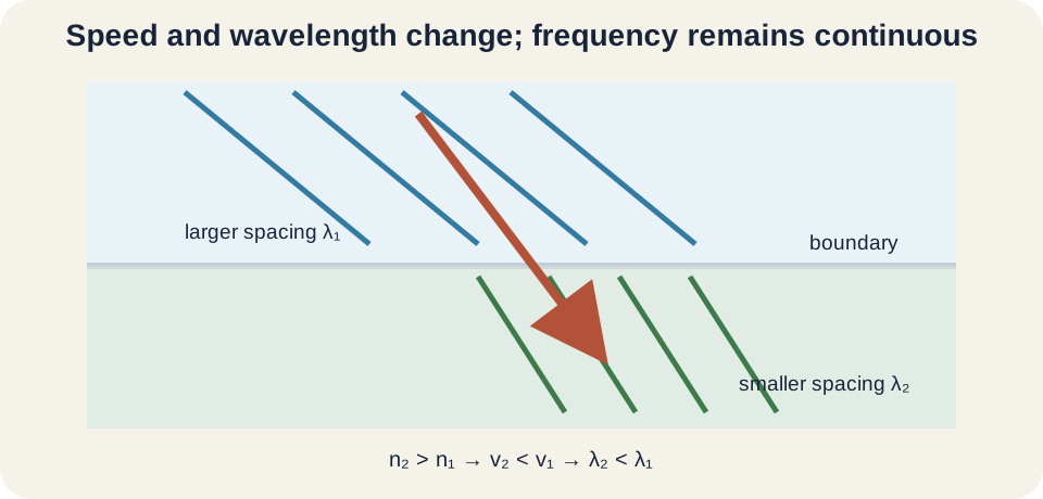
If vacuum wavelength is , the glass wavelength is in the simple nonmagnetic treatment. Frequency remains . Inside glass, produces the same frequency. The boundary changes speed and wavelength together. It does not change the source-driven oscillation rate.
Why frequency remains fixed
At a stationary boundary, electromagnetic fields on both sides must maintain compatible time variation along the interface. If reflected or transmitted waves had different frequencies from the incident wave, their phase relationship at the boundary would drift continuously. Ordinary linear, stationary material response therefore preserves frequency. The source sets the temporal oscillation rate. The media set phase speed and wavelength.
Use . When speed decreases and frequency stays constant, wavelength decreases in the same proportion. A larger refractive index therefore means a shorter wavelength at fixed vacuum frequency. Color perceived after light exits back into air is tied to frequency, not its shortened in-medium wavelength alone. The frequency returns no need to “change back” because it never changed.
Moving boundaries, nonlinear media, and inelastic scattering can shift frequency. Doppler effects occur when source, observer, or interface moves. Raman scattering exchanges energy with molecular vibrations. Fluorescence absorbs and re-emits at different frequencies. These processes lie beyond ordinary stationary-boundary refraction.
Reflection and transmission share energy
Snell’s law predicts transmitted direction but not how much energy enters each path. Fresnel equations determine reflection and transmission coefficients based on indices, angle, and polarization. Even clear glass reflects some light at normal incidence. The remainder may transmit or be absorbed. Energy accounting requires all channels.
At an air–glass boundary, reflected intensity is only a fraction of incident intensity for normal incidence. Multiple surfaces in a window can create several faint reflections. Anti-reflection coatings use interference to reduce reflection over selected wavelengths and angles. Their operation goes beyond a single-ray direction rule. Direction and intensity are separate outputs of boundary physics.
Polarization matters especially at oblique incidence. Electric-field orientation relative to the incidence plane changes reflection strength. At Brewster’s angle, one polarization has zero ideal reflection. This does not alter the basic Snell direction for the transmitted ray. It enriches the energy-partition story.
Critical angle and total internal reflection
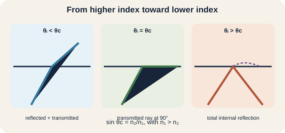
Total internal reflection requires light to travel from larger index toward smaller index . As incidence angle grows, the transmitted angle grows faster. The critical angle occurs when the transmitted ray reaches from the normal. Substituting into Snell’s law gives . Therefore with .
For glass with next to air with , . Incidence below this value produces both reflected and transmitted propagating rays. At the critical angle, the ideal transmitted ray runs along the interface. Beyond it, no propagating transmitted ray carries energy away into medium 2. Reflection becomes total in an ideal lossless model.
An evanescent field still penetrates a short distance into the lower-index medium. It decays exponentially rather than propagating away normally. Bringing another medium close can couple energy across the gap through frustrated total internal reflection. Thus “total” does not mean the field is exactly zero beyond the boundary. Elementary ray diagrams omit this wave-scale detail.
Optical fibers and practical total internal reflection
An optical fiber has a higher-index core surrounded by lower-index cladding. Rays within an accepted range strike the core–cladding boundary above its critical angle and remain guided. The cladding is essential because it creates a controlled lower-index interface. Merely surrounding glass with arbitrary material does not guarantee guidance. Input angle and mode structure also matter.
The ray picture is useful for large multimode fibers. A full wave description treats guided electromagnetic modes with field patterns across the core. Very narrow fibers may support only one spatial mode over a wavelength range. Bending can cause leakage if curvature disrupts confinement. Absorption and scattering cause additional attenuation.
Fiber communication uses light pulses to carry information over long distances. Different wavelengths and modes can travel with different group delays, causing dispersion. Repeaters or optical amplifiers compensate for loss. Medical endoscopes and illumination bundles use related guidance. Total internal reflection is a foundation rather than the entire engineering design.
Apparent depth follows ray reconstruction
An object under water often appears shallower when viewed from air at a modest angle. Rays leaving water bend away from the normal as they enter lower-index air. The observer’s visual system extrapolates the arriving rays backward along straight lines. Those extensions meet at a virtual image above the true object. The object has not physically moved.
For near-normal viewing and a flat interface, apparent depth is approximately . If the object is in water and observer in air, the ratio is about . A real depth of appears near . This relation is a small-angle approximation. Wider angles require explicit ray tracing with Snell’s law.
Refraction also explains why a partly submerged straight stick appears bent. Different portions send rays through different paths and interfaces. The boundary changes perceived direction at the surface. The effect is geometrical, not a deformation of the stick. Drawing two rays from one point locates the virtual image more reliably than verbal intuition.
Dispersion and color
Refractive index usually varies with frequency. In many transparent materials under visible-light conditions, shorter wavelengths have slightly larger index than longer wavelengths. Snell’s law then sends different colors along different angles. A prism spreads white light because its two nonparallel surfaces compound that angular separation. The spectrum was already present in the incident light.
Frequency remains fixed for each component at stationary boundaries. The phrase “blue slows more” refers to a greater phase-index response in the material, not a lower frequency. Wavelength inside changes according to each component’s speed. Upon returning to the same external medium, each recovers its external wavelength. The angular separation can persist because the paths have diverged.
Dispersion limits simple lens imaging because different colors focus at different positions, producing chromatic aberration. Compound lenses combine materials to reduce it. Rainbows involve refraction, dispersion, internal reflection, and geometry within water droplets. No single rule alone explains the full pattern. Complex phenomena can be decomposed into repeated boundary operations.
Common misconceptions and repairs
One misconception measures angles from the surface. Always draw a perpendicular normal and measure from it. An angle of from the surface is from the normal. Substituting the wrong complement changes every sine. Diagram labels should precede arithmetic.
Another misconception says a higher index always means the ray bends toward the normal. Direction depends on which medium it enters. Entering higher index bends toward, while entering lower index bends away. At normal incidence, neither case changes direction. Index comparison and incident side must both be stated.
A third misconception says total internal reflection happens whenever an incidence angle is large. It requires travel from higher to lower index and incidence exceeding the critical angle. From lower to higher index, would exceed one in the critical-angle expression, so no real critical angle exists. The sine-range test exposes the impossibility. Conditions are part of the law.
Practice with guided feedback
First, light travels from water with into air with at ; find the transmitted angle. Second, calculate the water–air critical angle. Third, state what happens to frequency and wavelength when light enters water from air. Fourth, explain why a ray at normal incidence does not bend. Include a normal on each sketch.
Snell’s law gives , so . Critical angle is . Entering water preserves frequency and reduces wavelength because speed decreases. At normal incidence the ray already lies along the normal, leaving no sideways component to change. All angles are measured from the normal.
Check direction before trusting numbers. Water to air should bend away, so must exceed . The incidence angle is below the critical value, so a transmitted ray is permitted. Sine inputs are dimensionless. Inverse sine returns the angle only after the physical branch is chosen.
Retrieval and connection forward
Without looking back, draw and label a complete boundary ray diagram. State the reflection law, refractive-index definition, and Snell’s law with every symbol explained. Use to describe what changes and what remains fixed. Derive the critical-angle equation and list both required conditions. Finish by explaining apparent depth through backward ray extension.
Lenses and mirrors use repeated reflection or refraction to form images. Diffraction and interference reveal when ray optics is insufficient. Wave optics explains thin-film coatings, polarization dependence, and evanescent fields. Electromagnetism derives boundary conditions from Maxwell’s equations. The ray model remains powerful when its wavelength-scale assumptions hold.
Keep one organizing statement: a boundary preserves wave phase along its surface, producing equal reflection angles and Snell’s refraction relation. Index measures relative phase speed, while stationary boundaries preserve frequency. Wavelength adjusts with speed. Total internal reflection emerges when Snell’s law has no propagating transmitted-angle solution. Geometry, energy partition, and wave behavior must be answered as related but distinct questions.